A Switch Mode Power Supply converts electrical energy by rapidly switching semiconductor devices and shaping the output with components such as inductors, transformers, and capacitors. Compared with many linear designs, it can deliver efficient power in a compact enclosure. You might find one inside a router, LED fixture, industrial control cabinet, or battery-powered instrument. The label sounds simple. The design choices are not.
This guide explores ten common types, including AC-to-DC and DC-to-DC supplies, buck and boost converters, flyback and forward designs, and resonant supplies. These names do not all describe the same thing: some identify a circuit topology, while others describe the input and output or a product’s function. Categories can overlap. That distinction matters when comparing specifications or choosing a unit for a real load.
A useful comparison starts with the input-voltage range, required output, isolation needs, load behavior, thermal conditions, and available space. Check the datasheet, not just the product label. A small supply may fit neatly on a crowded board yet run hot under sustained load. A high-efficiency rating can also hide limitations at light loads or during startup. The best option depends on the application, and no single type wins everywhere. Even experienced designers revisit assumptions when the actual operating conditions differ from the bench test.
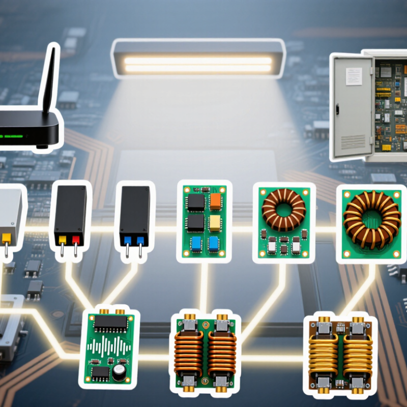
Top 10 Types of Switch Mode Power Supply
Definition and Operating Principles of Switch-Mode Power Supplies
A switch-mode power supply (SMPS) converts electrical energy by rapidly switching transistors on and off. Unlike a linear supply, it regulates voltage by controlling energy pulses rather than dissipating excess energy as heat. An inductor or transformer stores and transfers energy; capacitors smooth the output. A feedback circuit senses voltage changes and adjusts the switching duty cycle. The result can be a compact, efficient supply. That is the core.
Common topologies include buck, boost, buck-boost, flyback, forward, push-pull, half-bridge, full-bridge, resonant, and PFC-assisted designs. Each suits different input ranges, output power, isolation, and cost needs. The U.S. Department of Energy’s external power supply test procedure measures active-mode efficiency at 25%, 50%, 75%, and 100% load. These checkpoints matter because a supply’s performance can shift with its operating load. A printed efficiency figure alone may not describe behavior on a lightly loaded bench. One caveat: switching noise and heat still need careful control. A neat block diagram can hide messy layout details.
Switch mode power supplies are classified by what they convert and whether input and output are electrically isolated. For DC-to-DC conversion, five common non-isolated topologies are buck, boost, buck-boost, Ćuk, and SEPIC. A buck circuit steps voltage down; a boost circuit raises it. Buck-boost, Ćuk, and SEPIC designs handle broader voltage relationships, though their component stresses and control needs differ. No isolation barrier. A copper inductor, switching transistor, and output capacitor are easy to picture on a bench; their layout still affects heat and electrical noise.
Five widely used isolated types are flyback, forward, push-pull, half-bridge, and full-bridge. A high-frequency transformer transfers energy while separating input and output circuits. Flyback designs suit compact, lower-power supplies; bridge designs often fit higher-power conversion, with more switches and control complexity. The categories overlap in practice: input range, load, safety needs, cost, and thermal limits can change the best choice. That judgment is rarely tidy.
Efficiency makes the choice consequential. Lawrence Berkeley National Laboratory’s 2024 United States Data Center Energy Usage Report estimates U.S. data centers used about 176 terawatt-hours in 2023, or roughly 4.4% of national electricity. This is not an SMPS-only figure, but it shows why conversion losses matter at scale. Topology alone does not guarantee efficiency; switching frequency, magnetic design, and light-load behavior matter too. A neat “top ten” list helps, but real hardware often resists neat labels.
| # | Topology | Conversion type | Galvanic isolation | Typical operating principle | Common applications and design notes |
|---|---|---|---|---|---|
| 1 | Buck (step-down) | Non-isolated DC–DC conversion; output voltage is lower than input in normal operation. | No | A controlled switch, inductor, and output capacitor transfer and smooth energy. In an ideal continuous-conduction buck, output voltage is approximately input voltage multiplied by duty cycle. | Widely used for point-of-load regulators and intermediate bus conversion. Efficient when stepping down, but the input and output share a common electrical reference. |
| 2 | Boost (step-up) | Non-isolated DC–DC conversion; output voltage is higher than input in normal operation. | No | The inductor stores energy while the switch is on and releases it to the output when the switch turns off. The ideal output-to-input ratio rises as duty cycle increases. | Common in battery-powered equipment and power-factor-correction front ends. A conventional boost cannot regulate its output below the input voltage. |
| 3 | Buck–boost | Non-isolated step-up or step-down DC–DC conversion; the classic single-switch form inverts output polarity. | No | Energy is stored in an inductor during part of the switching cycle and delivered to the output during another part. The output magnitude can be above or below the input. | Useful when an input range crosses the required output voltage. Non-inverting buck–boost variants are also available, but use different circuit arrangements. |
| 4 | Flyback | Isolated, transformer-coupled buck–boost-derived conversion. | Yes | The transformer’s magnetic core stores energy while the primary switch conducts; that energy is transferred to the secondary after the switch turns off. | A common choice for low-to-medium-power isolated supplies and multiple outputs. It has a relatively simple power stage, while transformer design and peak currents require care. |
| 5 | Forward | Isolated, transformer-coupled buck-derived conversion. | Yes | When the primary switch is on, energy is transferred through the transformer to the secondary and output inductor. A reset mechanism is needed to remove magnetizing energy from the core. | Used in isolated DC–DC converters where a separate output inductor provides relatively continuous output current. Reset winding, clamp, or other reset arrangements add design considerations. |
| 6 | Push–pull | Isolated, transformer-coupled two-switch conversion. | Yes | Two switches alternately drive opposite halves of a center-tapped transformer primary, producing alternating transformer flux and secondary power pulses. | Often used in lower-to-medium-power isolated converters, including some battery-fed designs. Unequal drive timing or winding imbalance can cause flux walking and core saturation. |
| 7 | Half-bridge | Isolated, transformer-coupled bridge conversion. | Yes | Two switches apply alternating voltage to the transformer primary, typically using a split DC bus or equivalent capacitor arrangement. The transformer transfers energy to the secondary. | Suitable for medium-power isolated supplies. It uses fewer primary switches than a full bridge, but switch voltage stress and DC-bus balance must be considered. |
| 8 | Full-bridge | Isolated, transformer-coupled bridge conversion. | Yes | Four primary switches operate in diagonal pairs to apply alternating polarities across the transformer primary. A secondary rectifier and filter produce DC output. | Common in higher-power isolated converters. It makes good use of the transformer but requires more switches and careful control to prevent shoot-through. |
| 9 | SEPIC | Non-isolated, step-up/step-down DC–DC conversion; output polarity is non-inverting. | No | A series energy-transfer capacitor and inductors allow the output voltage to be either higher or lower than the input while retaining the input’s polarity. | Useful when the input varies above and below the regulated output. It typically has more components and circulating energy than a basic buck or boost converter. |
| 10 | Ćuk | Non-isolated, step-up/step-down DC–DC conversion; the classic form inverts output polarity. | No | A capacitor transfers energy between the input and output inductors. In continuous-conduction operation, both input and output inductor currents can be relatively smooth. | Chosen when low input-current ripple is important. The classic topology produces an inverted output and requires two inductors and an energy-transfer capacitor. |
Note: “Isolated” indicates galvanic separation through a transformer or another isolation element. Actual performance, power capability, and voltage range depend on the specific circuit design and components.
Ten common SMPS designs differ in how they switch energy and control voltage.
A buck converter uses a switch, inductor, and diode or synchronous switch to step voltage down. A boost converter stores energy in an inductor, then releases it at a higher output voltage. Buck-boost designs can raise or lower voltage, though some versions invert polarity. SEPIC circuits also step voltage up or down while keeping output polarity unchanged. These are common choices for compact DC power stages.
Flyback converters store energy in a coupled inductor while the switch is on, then transfer it to the output when the switch turns off. Forward converters transfer energy directly through a transformer during the on-time. Push-pull designs alternate two switches across a transformer. Half-bridge and full-bridge circuits use two and four main switches, respectively, for transformer-based conversion. LLC resonant converters use an inductor-capacitor network to shape switching transitions and reduce losses.
The neat diagram is not the whole story; layout and heat can change real-world performance.
Tips: Check input range, output current, isolation needs, and thermal limits before choosing a topology. Inspect the switching waveform and component temperatures under load. A design that works on paper may still need careful tuning.
Top 10 Types of Switch Mode Power Supply: Typical Applications and Strengths of Each SMPS Type
AC-DC supplies convert wall power for appliances, chargers, and control equipment; DC-DC converters regulate voltage between battery and circuit stages. Isolated designs add a safety barrier, useful in medical, industrial, and communications equipment. Non-isolated designs are smaller and efficient when input and output can share a ground. Different jobs.
Flyback converters suit compact, lower-power adapters and provide multiple outputs with few components. Forward converters handle steadier, higher power. Push-pull designs work well in battery-fed systems, while half-bridge and full-bridge topologies serve progressively higher-power industrial supplies. Resonant converters can reduce switching losses and heat in servers and fast chargers. No topology wins everywhere.
The Lawrence Berkeley National Laboratory’s 2024 United States Data Center Energy Usage Report estimates U.S. data centers used 176 TWh in 2023, about 4.4% of national electricity. That scale makes server power conversion efficiency consequential. Yet a high-efficiency figure at one load point can mislead: real equipment moves between idle and peak demand. A neat datasheet is not the whole story. Engineers should check thermal behavior, load range, isolation needs, and service conditions before choosing a supply.
The chart compares the typical number of main power switches in common implementations; variants may differ. Topology choice also depends on power level, isolation, input and output voltage, efficiency, and cost.
Switch-mode power supplies use different circuit topologies, and their names hint at different trade-offs. Buck converters step voltage down; boost converters raise it, while buck-boost and SEPIC designs can handle changing input levels. Flyback and forward converters provide isolation in many designs. Push-pull, half-bridge, and full-bridge circuits suit progressively higher power needs, while resonant designs can reduce switching losses under suitable conditions.
Efficiency figures need context. Compare performance at the input voltage and load your equipment will actually use, not only at a quoted peak. A supply may run efficiently at full load yet waste more energy when powering a lightly loaded device. Check temperature too: a warm enclosure after an hour can reveal losses that a brief test misses. That matters.
Output requirements shape the choice. A small sensor may need steady low-voltage DC, while a motor controller can demand rapid changes in current. Ripple, regulation, startup behavior, and response to sudden load changes all deserve attention. Safety is not guaranteed by a topology name. For isolated designs, review the specified isolation rating, clearances, protection features, and intended operating environment. Compare documented test conditions, not just headline specifications. A tidy table helps, though real operating conditions can still surprise you.
It converts electrical energy by switching transistors rapidly on and off. Inductors or transformers transfer energy, while capacitors smooth the output. That is the basic idea.
A feedback circuit senses voltage changes and adjusts the switching duty cycle. The circuit responds to the load, though real performance depends on layout and heat.
A buck converter steps voltage down. A boost converter raises it. Simple distinction. Component stress still matters.
Yes. Buck-boost and SEPIC designs can do both. Some buck-boost versions invert output polarity; SEPIC keeps the output polarity unchanged.
Flyback, forward, push-pull, half-bridge, and full-bridge designs use a high-frequency transformer to separate input and output circuits. Isolation needs affect the choice.
A flyback converter stores energy while its switch is on, then transfers it to the output when the switch turns off. A forward converter transfers energy through the transformer during the on-time.
These transformer-based designs often suit higher-power conversion. A half-bridge uses two main switches; a full-bridge uses four. More switches bring added control complexity.
Check the input range, output current, isolation needs, and thermal limits. Inspect waveforms and component temperatures under load. Paper calculations are not enough.
Not always. Efficiency can change with load, so measurements at 25%, 50%, 75%, and 100% load offer useful checkpoints. Light-load behavior can still surprise you.
A Switch Mode Power Supply (SMPS) converts electrical power by rapidly switching semiconductor devices and using inductors, capacitors, and, in some designs, transformers to regulate the output. Its topologies can be grouped by conversion function—step-down, step-up, or step-up/step-down—and by whether they provide electrical isolation. Ten common types are buck, boost, buck-boost, Ćuk, SEPIC, flyback, forward, push-pull, half-bridge, and full-bridge converters. Each uses a different circuit arrangement to manage voltage, current, and energy transfer.
These designs suit different needs: buck converters provide lower voltages efficiently, while boost and SEPIC designs can raise voltage; isolated transformer-based topologies are useful when separation between input and output is needed. Applications range from compact electronics and battery-powered equipment to higher-power systems. Choosing among them involves balancing efficiency, output range and stability, component complexity, size, cost, and safety requirements. The best topology depends on the source, load, power level, and whether isolation is essential.