What Engineering Buyers Must Know Before Sourcing an Inverter with Battery Charger
In modern industrial automation, telecom base stations, commercial vehicle retrofits, and off-grid renewable infrastructure, power reliability hinges entirely on the seamless coordination between DC storage, grid mains, and AC output loads.
An inverter with battery charger (commonly designated as an inverter/charger, bidirectional power conversion system, or combi-inverter) integrates three distinct core electrical subsystems into a unified, thermally-managed chassis: a bidirectional high-frequency or low-frequency pure sine wave DC-to-AC power inverter, an intelligent multi-stage utility-to-DC battery charger with active Power Factor Correction (PFC), and an ultra-fast internal Automatic Transfer Switch (ATS). When the primary AC grid or auxiliary diesel genset is operational, the unit routes grid AC directly to the downstream loads while simultaneously regulating a multi-stage charging algorithm to replenish connected energy storage banks. The moment AC utility power fluctuates, sags beyond voltage tolerances, or experiences complete blackout, the transfer relay decouples the utility connection and transfers the load to the DC-to-AC inversion circuit in typically less than 10 milliseconds, preventing microprocessor resets and inductive motor stalls.
For procurement directors, OEM product managers, and project electrical engineers, selecting an inverter with battery charger involves navigating complex trade-offs between low-frequency copper transformer topologies and high-frequency Silicon Carbide (SiC) switching systems, closed-loop BMS communication protocols (CANBus 2.0B / RS485 Modbus RTU), multi-chemistry charging algorithms (specifically LiFePO4 vs. AGM/Gel lead-acid), and strict international electromagnetic compliance (EMC EN 61000-6-2/4 and LVD EN 62368-1). Yueqing Keldan Technology Co., Ltd. leverages over 18 years of manufacturing expertise in Yueqing, Zhejiang, to deliver factory-direct engineering customizability, verified lifecycle durability, and predictable B2B supply chain integrity.
Factory Direct Series
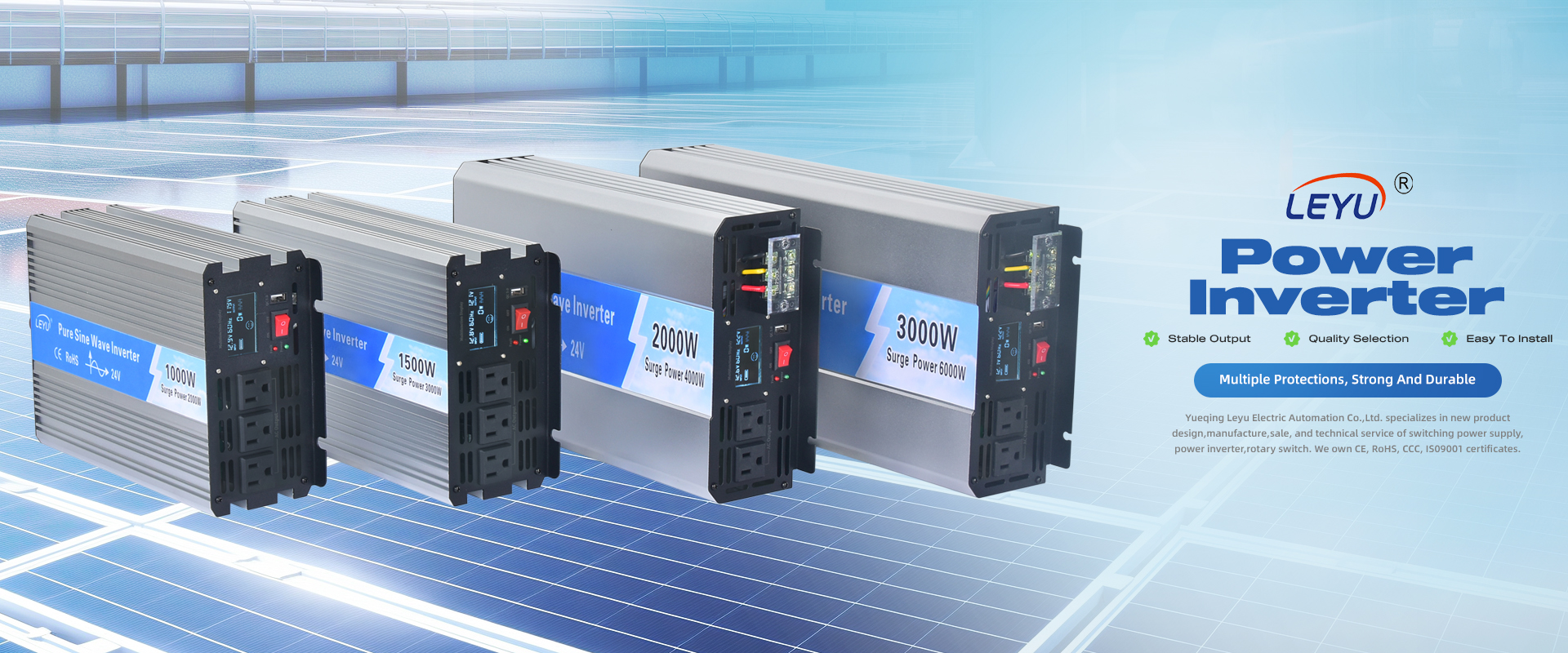
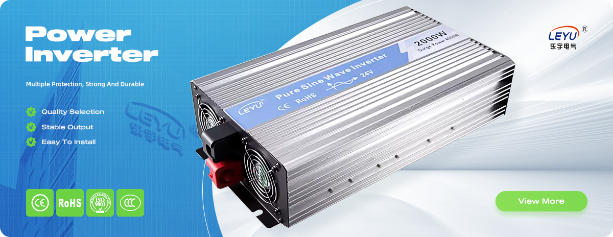
Engineered Inverter with Battery Charger Product Portfolio
Field-proven topologies built with tier-one semiconductors, high-permeability magnetic cores, and integrated smart multi-stage battery chargers.
KIC-Pro Series (1kW–3kW)
Compact High-Frequency Inverter with Smart PFC Battery Charger
Optimized for specialty vehicles, RV retrofits, and telecom cabinets. Features continuous 12V/24V/48V pure sine wave output, 30A–60A configurable charging currents, and sub-10ms transfer.
Low-Frequency Toroidal Inverter Charger with 300% Surge Rating
Engineered with low-loss copper toroidal isolation transformers for high-inrush motor loads, refrigeration compressors, industrial pumps, and marine power systems.
All-In-One Hybrid Inverter Charger with Integrated PWM/MPPT
Unifies solar PV harvesting, utility grid battery replenishment, and uninterrupted AC power delivery. Complete with programmable charging source priorities (Solar First / Utility First).
Technical Criteria for Specifying an Inverter with Battery Charger
Prevent field warranty claims, thermal runaways, and equipment failure through rigorous parametric engineering.
1. Charger Topology & PFC
Modern inverter chargers must incorporate active Power Factor Correction (PFC > 0.95) within the AC-to-DC stage. Without active PFC, distorted non-linear charging currents cause severe generator harmonic resonance, thermal tripping of breakers, and significant unmetered reactive power penalties.
2. High-Frequency vs. Toroidal
High-frequency MOSFET units offer high power density and compact weight for mobile installations, while heavy low-frequency toroidal transformer units deliver unmatched galvanic isolation, enduring 300% peak inductive surge currents for up to 20 seconds without commutation collapse.
3. Closed-Loop BMS Protocol
With global energy systems transitioning rapidly from lead-acid to Lithium Iron Phosphate (LiFePO4), open-loop voltage sensing is no longer adequate. Specifying native CANBus 2.0B or RS485 Modbus RTU communication allows the BMS to dynamically dictate real-time charge voltage and current limits.
4. Transfer Time & Phase Sync
Seamless operation of IT hardware and industrial PLCs requires transfer times below 10 milliseconds. Units must incorporate zero-crossing phase synchronization to prevent back-EMF phase opposition arcs across transfer relay contacts during sudden grid transitions.
Comprehensive Engineering Comparison: Inverter with Battery Charger Series
Electrical Parameter
High-Frequency Series (KIC-HF)
Low-Frequency Toroidal Series (KIC-LF)
Hybrid Energy Series (KIC-HY)
Continuous Rated Power
1,000W – 3,500W
2,000W – 6,000W
3,000W – 8,000W
Surge Capacity (Peak Rating)
200% for 100 milliseconds
300% for 20 seconds
200% for 5 seconds
Inverter AC Output THD
< 3% (Linear Load), < 5% (Non-linear)
< 2.5% (Ultra-pure sinusoidal)
< 3% (Linear Load)
AC Charger Topology
Smart Switch-Mode PFC (PF > 0.98)
SCR / Linear Multi-Stage with PFC
Bidirectional PWM/MPPT Hybrid
Battery Chemistries Supported
LiFePO4, Ternary Lithium, AGM, GEL, Flooded
LiFePO4, AGM, GEL, Deep-Cycle Lead
Lithium-ion Pack, LiFePO4, Sealed Lead
Transfer Time (Grid to Inverter)
< 8 milliseconds (UPS Grade)
< 10 milliseconds
< 10 milliseconds (Zero-crossing)
Communication Interfaces
RS485 Modbus RTU, Optional Dry Contact
CANBus 2.0B, RS485, Generator Auto-Start
CAN, RS485, Wi-Fi IoT Cloud Module
Typical Target Applications
Service Vans, Marine Yachts, Telecom Cabinets
Cold Storage, Water Pumps, Heavy Automation
Off-grid Residential, Rural Microgrids
Market Intelligence & Forecasting
Future Procurement Trends & Technology Trajectories for Inverter Chargers
How wide-bandgap semiconductors, bidirectional grid connectivity, and strict energy security regulations are reshaping the global procurement landscape through 2030.
1. Wide-Bandgap GaN & SiC Topologies
The commercial power electronics industry is rapidly transitioning from traditional silicon insulated-gate bipolar transistors (IGBTs) toward Silicon Carbide (SiC) and Gallium Nitride (GaN) MOSFET architectures. In an inverter with battery charger, operating switching frequencies can now exceed 100 kHz without incurring massive switching losses. For procurement teams, this delivers three tangible advantages: physical enclosure volume and chassis weight are reduced by more than 35%, conversion efficiency jumps from ~89% to beyond 95%, and acoustic noise is practically eliminated. Yueqing Keldan Technology Co., Ltd. is actively designing compact SiC modules to satisfy high-density customer project requirements.
2. True Bidirectional Power Conversion
Historically, an inverter/charger utilized two separate circuit stages: an H-bridge DC-to-AC inverter and a dedicated AC-to-DC buck rectifier. Future procurement is pivoting decisively toward single-stage bidirectional topologies (Dual Active Bridge - DAB or bidirectional totem-pole PFC). By utilizing the identical magnetic core and semiconductor array to handle both charging and discharging paths, component count is lowered by 25%, drastically enhancing mean time between failures (MTBF) while unlocking dynamic peak-shaving capabilities for smart microgrids.
3. Edge AI Diagnostics & Predictive Maintenance
Tier-one infrastructure buyers are no longer satisfied with simple LED display status indicators. Advanced inverter chargers now integrate onboard 32-bit DSP controllers capable of real-time thermal modeling, electrolytic capacitor ESR degradation tracking, and automated relay contact resistance calculation. When connected via IoT gateways, engineering managers receive early warning alerts before field component degradation leads to unexpected commercial downtime.
4. Grid Code Compliance & Cybersecurity
As decentralized battery storage assets interconnect with regional electricity networks, regulatory bodies in North America (UL 1741 SA/SB) and the European Union (EN 50549-1) demand anti-islanding protection, low-voltage ride-through (LVRT), and encrypted communication protocols. B2B procurement specifications increasingly stipulate secure cryptographic hardware elements to protect connected power infrastructures against unauthorized network interventions.
Manufacturing Authority & Reliability
Why Global B2B Buyers Partner with Yueqing Keldan Technology Co., Ltd.
Direct from China's primary electrical capital in Yueqing, Wenzhou. Onsite-verified by TÜV Rheinland to ensure uncompromised manufacturing standards.
Verified Custom Manufacturer
Engineered Precision from Raw SMT to Final Burn-In
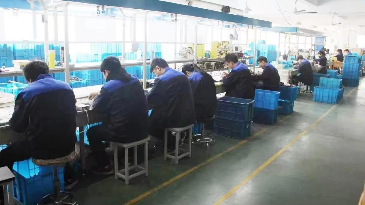
Yueqing Keldan Technology Co., Ltd. operates a specialized production facility staffed by 44 verified personnel, including dedicated power electronics R&D engineers with more than five years of SMPS and inverter design expertise. Unlike assembly brokers or trading middlemen, we control the entire lifecycle of our conversion electronics on our own factory floor.
Our comprehensive manufacturing workflow encompasses automated SMT surface-mount placement, precision reflow soldering ovens, Automated Optical Inspection (AOI) to eliminate microscopic solder bridges, hand-assembly of magnetic components, and 100% full-load thermal burn-in aging tests. This guarantees that every inverter with battery charger shipped to our partners in Europe, the Americas, and Australasia operates flawlessly under harsh environmental conditions.
TÜV Rheinland verified on-site facility
Full OEM/ODM design from schematic to chassis
Automated SMT & AOI optical verification
Dedicated full-load burn-in aging racks
Custom charge curves for lithium & lead-acid
10+ years of dedicated international export service
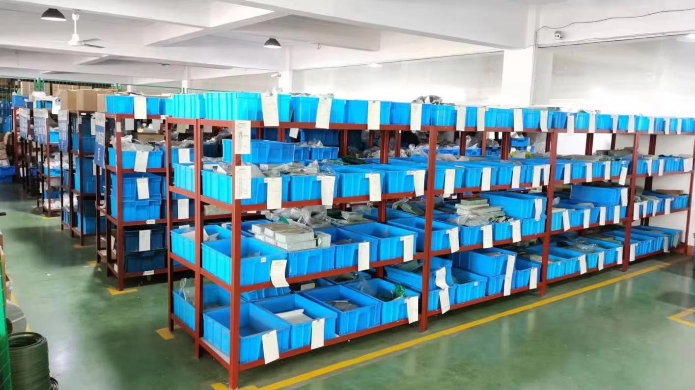
Verified Production Line & Quality Control Equipment
Photographic proof of in-house manufacturing capabilities at Yueqing Keldan Technology Co., Ltd.
Procurement FAQ
Frequently Asked Questions by Global Buyers & Engineers
Clear, unhedged technical answers to the most common questions raised during the quotation and engineering specification phase.
What is the fundamental difference between an inverter with a built-in charger and a standalone inverter with a separate battery charger?
An integrated inverter with battery charger incorporates an internal high-speed Automatic Transfer Switch (ATS) and a common microprocessor control logic that coordinates AC pass-through, battery replenishment, and inversion seamlessly. When separate units are paired, the installer must provide external transfer contactors, interlocking relays, and separate cabling, which increases installation time, introduces wiring failure points, and frequently leads to ground loops or transfer delays exceeding 30–50ms. Integrated units offer coordinated thermal management, synchronized phase switching, and a smaller overall volumetric footprint.
How does the internal Automatic Transfer Switch (ATS) protect sensitive electronic loads during a grid blackout?
Standard industrial units by Yueqing Keldan Technology Co., Ltd. feature a transition time of less than 8 to 10 milliseconds. Because switch-mode power supplies (such as those in servers, PLCs, and medical monitors) are engineered with hold-up capacitors capable of maintaining output bus voltage for 16 to 20 milliseconds according to Intel ATX and IEC 61000 standards, an 8ms transfer occurs well within the holdup margin. This guarantees that downstream microcontrollers and sensitive automated systems experience zero disruption or reboot cycles.
Can an inverter with battery charger be configured for Lithium Iron Phosphate (LiFePO4) battery banks without voiding the warranty?
Yes. Unlike older multi-stage chargers hardcoded strictly for flooded or AGM lead-acid profiles, our inverter chargers provide either user-programmable charge voltage setpoints (Constant Current / Constant Voltage parameters without equalization cycles) or direct digital communications via CANBus 2.0B / RS485 Modbus RTU to interface directly with your Battery Management System (BMS). This prevents dangerous overvoltage cell stress and low-temperature charging damage.
How do low-frequency (transformer-based) and high-frequency inverter chargers compare in motor-start applications?
Low-frequency models utilize large iron-core or toroidal electromagnetic transformers that provide natural galvanic isolation and substantial thermal mass. They can easily sustain up to 300% of their continuous power rating for 20 seconds to overcome locked-rotor inductive surges from air conditioners, compressors, and hydraulic pumps. High-frequency models utilize smaller ferrite cores and electronic switching circuits; while significantly lighter and more cost-effective for resistive loads and electronics, they typically cap surge capability at 150–200% for a fraction of a second.
What certifications and quality compliance documents does Yueqing Keldan Technology Co., Ltd. provide?
All our primary conversion models carry European CE marking, conforming directly to the Low Voltage Directive (LVD EN 62368-1) and Electromagnetic Compatibility (EMC EN 61000-6-2 for immunity and EN 61000-6-4 for emissions). Furthermore, our manufacturing facility has undergone rigorous on-site audit verification by TÜV Rheinland, validating our quality assurance protocols, SMT lines, and burn-in testing infrastructure. Formal test reports and declaration of conformity files are provided with procurement agreements.
What are the OEM/ODM customization options and minimum order quantities (MOQs)?
We support full turnkey OEM/ODM modifications, including custom DC input voltages (12V, 24V, 36V, 48V, 72V, 96V), custom AC output voltages (100V, 110V, 120V, 220V, 230V, 240V at 50/60Hz), custom metal enclosure chassis, silk-screened client branding, specialized terminal blocks, and custom firmware charge algorithms. Evaluation sample orders are accepted starting at 1 piece, while standard volume OEM custom production typically begins from 50 to 100 units depending on the complexity of chassis retooling.
Ready to Source High-Reliability Inverter Charger Systems?
Connect directly with the electrical engineering and sales support team at Yueqing Keldan Technology Co., Ltd. Submit your specifications for continuous power, surge envelope, charging profiles, or custom enclosures today.