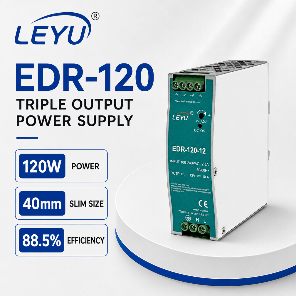
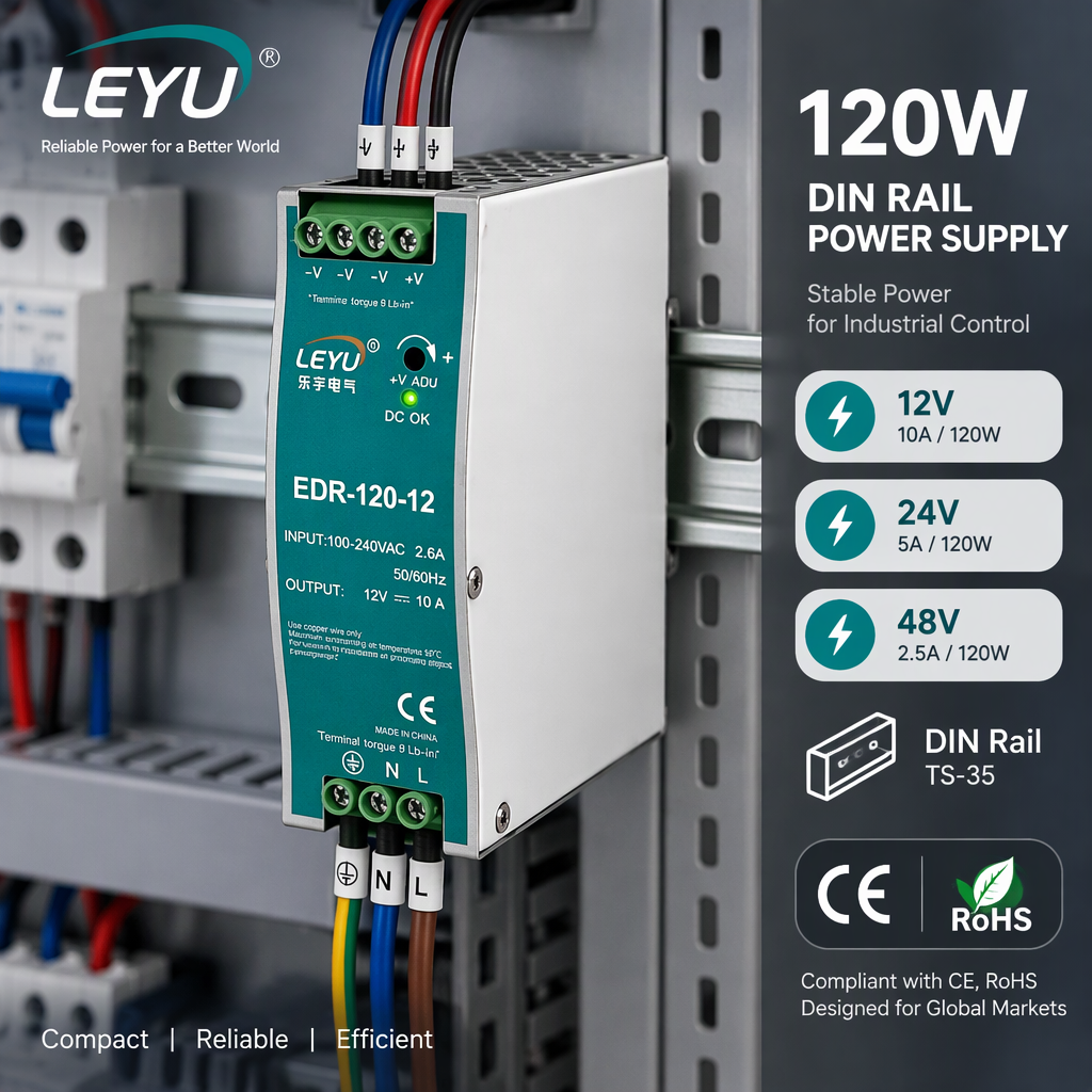
EDR-120 120W Industrial DIN Rail Power Supply 12V 10A 24V 5A 48V 2.5A AC DC Switching Power Supply for PLC Control Cabinet
- Output Channels: 12V / 24V / 48V
- Conversion Eff.: Up to 88.5%
- Form Factor: TS-35/7.5 or 15
- Protection: Short / Overload / OVP
Precision-regulated AC/DC converters, TS-35 DIN rail mounting supplies, and heavy-duty IP67 LED power solutions manufactured with strict compliance to CE, RoHS, and international safety protocols.
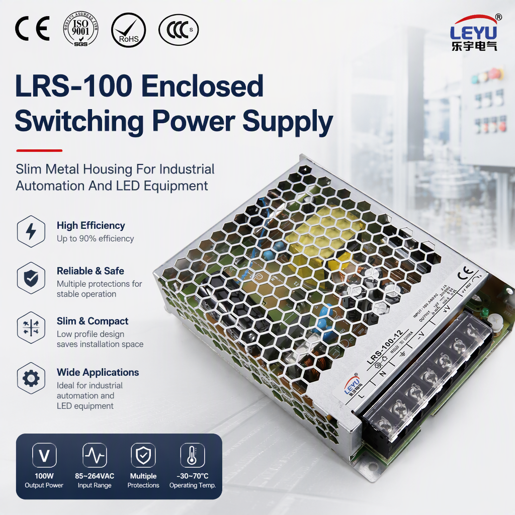
An authoritative analysis of circuit topologies, active power factor correction (PFC), thermal dissipation dynamics, and harmonic compliance standards for global electrical importers.
In the contemporary landscape of international power electronics commerce, the distinction between a commercial trading entity and an authentic original equipment manufacturer (OEM) hinges upon deep topological competence. Switched-Mode Power Supplies (SMPS) operating in commercial LED lighting, industrial programmable logic controller (PLC) enclosures, and building automation hubs are subject to extreme line fluctuations, electromagnetic interference (EMI), and elevated thermal ambient loads. As China's premier manufacturer and exporter based in Yueqing, Wenzhou—the worldwide epicenter for low-voltage electrical apparatus—Yueqing Keldan Technology Co., Ltd. builds its complete product taxonomy upon validated electrical engineering fundamentals rather than cut-corner assembly.
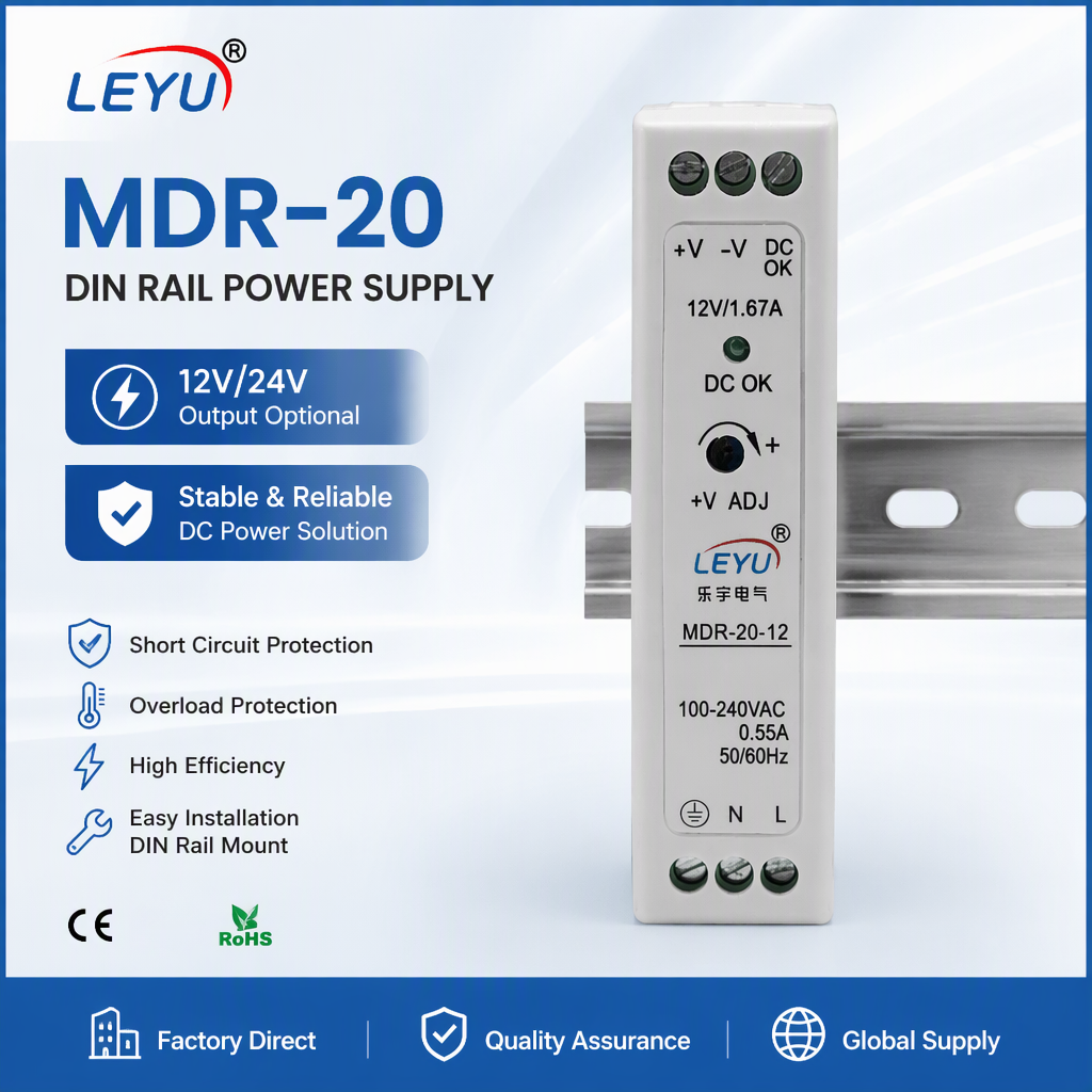
Selecting an optimal switching topology dictates the energy efficiency, physical profile, electromagnetic radiation envelope, and long-term mean time between failures (MTBF) of the power converter. For sub-100W enclosed and DIN-rail systems (such as the MDR-20 and lower-wattage enclosed units), quasi-resonant discontinuous flyback topologies deliver exceptional cost-to-performance metrics, utilizing minimal passive magnetic components while providing galvanic isolation compliant with IEC 62368-1 and EN 61347-2-13.
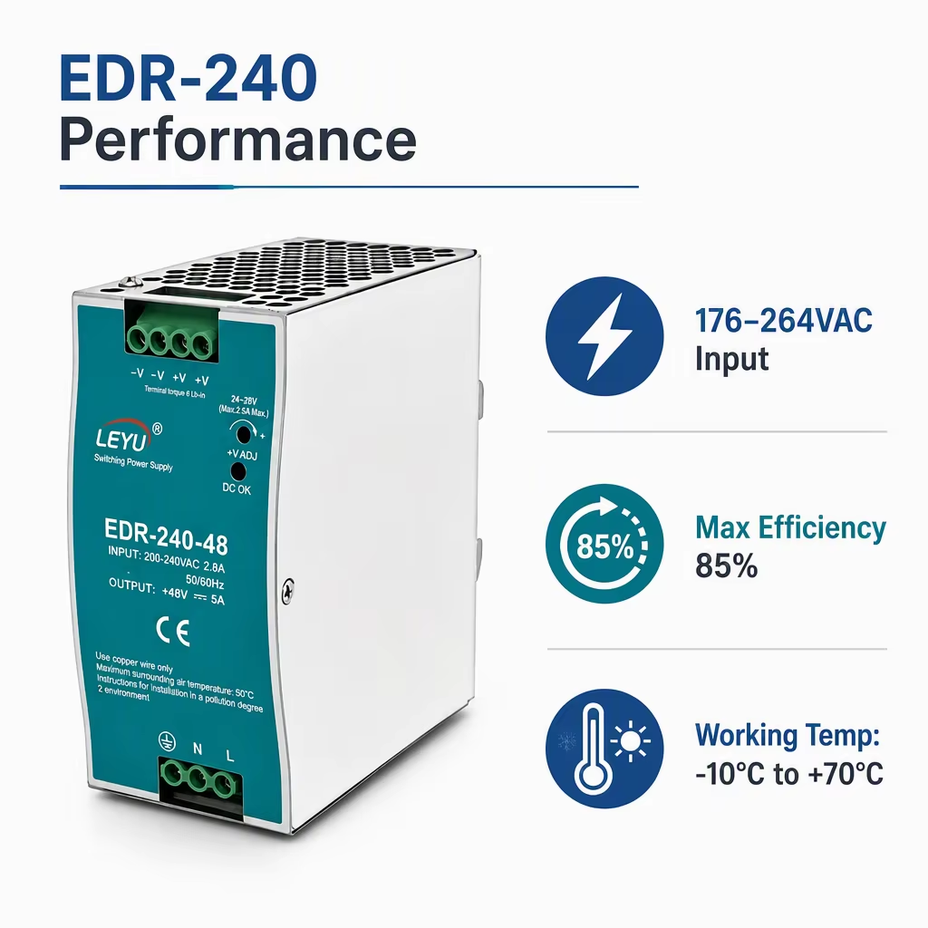
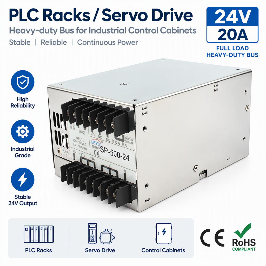
However, when procurement specifications escalate into high-power commercial horticultural arrays, architectural linear LED runs, and heavy-duty automation panels spanning 200W to 500W (embodied in our EDR-240 and SP-500-12 configurations), classic flyback converters exhibit excessive drain-to-source voltage spikes and secondary rectifying diode switching losses. Here, Keldan leverages Active PFC Boost stages coupled with Half-Bridge LLC Resonant Converters. By achieving Zero Voltage Switching (ZVS) across the primary MOSFET switches and Zero Current Switching (ZCS) across the secondary synchronous rectifiers, switching losses are virtually neutralized. This topology elevation is the direct technical foundation enabling our EDR-240 series to register peak operational efficiencies up to 95%, dramatically minimizing thermal waste inside unventilated IP67 luminaire casings or cramped TS-35 electrical distribution cabinets.
| Circuit Topology | Typical Power Band | Efficiency Benchmark | PFC Stage Implementation | Primary Target Application |
|---|---|---|---|---|
| Quasi-Resonant Flyback | 15W – 90W | 84% – 88.5% | Passive Valley Fill or Single-Stage | MDR-20 DIN Rail, CCTV Auxiliaries, Compact Smart Home Sensors |
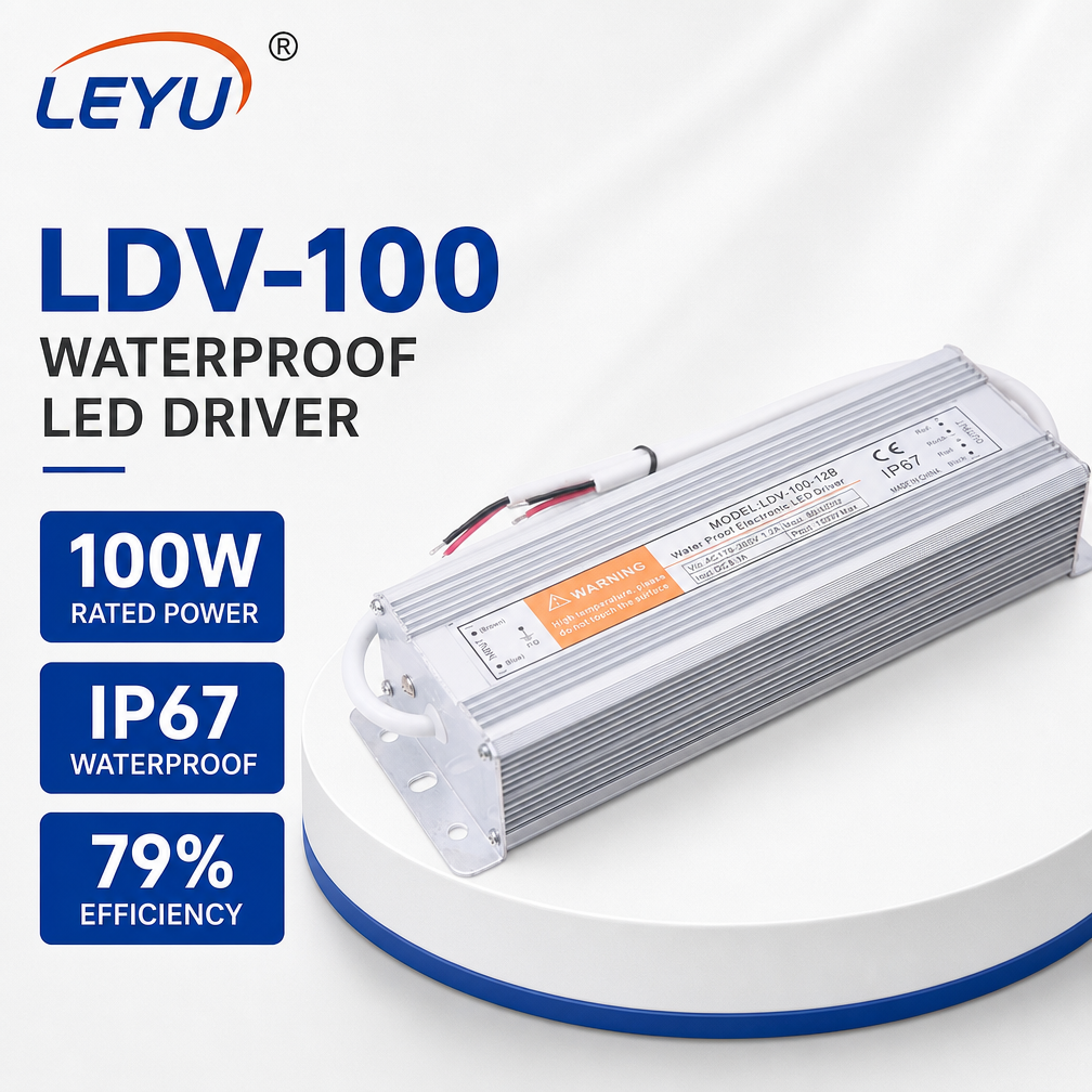
| Two-Switch Forward | 100W – 250W | 88% – 91% | Continuous Conduction (CCM) Boost PFC | EDR-120 Series, LDV-100 Waterproof Outdoor LED Drivers |
| Half-Bridge LLC Resonant | 200W – 600W | 92% – 95.5% | Interleaved Critical Conduction / CCM PFC | EDR-240, SP-500 Industrial Enclosed, High-Mast Flood Lighting |
| Full-Bridge Phase Shifted | 600W – 3000W+ | 94% – 96.5% | Active Bridgeless Totem-Pole PFC | Centralized DC Microgrids, Telecommunication Plant Inverters |
Stringent global import tariffs and efficiency directives—specifically the European Ecodesign Directive (EU) 2019/2020 (ErP Lot 7), US Title 24, and Energy Star specifications—mandate stringent input power quality. In an uncorrected capacitive rectifier circuit, current is drawn only at the crest of the sinusoidal AC voltage wave, generating severe third-order and higher harmonic currents that distort the municipal electrical grid and cause neutral line overheating in large-scale commercial facilities.
Keldan's SP-500 series and advanced LED switching supplies incorporate an automated active power factor correction controller that reshapes the input current wave into precise phase with the mains voltage. This achieves a Power Factor (λ) greater than 0.98 at rated load, while driving Total Harmonic Distortion (THD) under 10% across the universal input envelope of 90VAC to 264VAC. This level of harmonic mitigation guarantees complete compliance with EN 61000-3-2 Class C standards for lighting equipment, safeguarding tier-one EPC contractors from administrative border rejections or facility-level EMI non-compliance penalties.
Navigating the structural transition toward wide-bandgap semiconductors, decentralized DC building grids, bidirectional power architectures, and real-time telemetry integration.
Procurement teams are shifting away from traditional planar silicon MOSFETs. GaN switches allow switching frequencies above 250kHz with minimal gate charge losses, shrinking high-frequency planar transformer footprints by 40% while sustaining exceptional power density inside ultra-thin enclosure profiles.
Modern smart warehouses and smart buildings are progressively discarding multiple localized AC-to-DC steps in favor of centralized class-2 48V bus systems. Our EDR series with native 48V 2.5A outputs fulfills this rapid architectural shift, mitigating copper conductor losses while facilitating direct coupling with renewable battery storage banks.
The era of "dumb" static power supplies is coming to an end. Tier-one procurement criteria now frequently specify DALI-2, PMBus, or Modbus protocol integration over RS-485. Engineers require active telemetry on junction temperatures, operational hours, input surge peaks, and dynamic capacitor degradation monitoring.
Extreme climatic deployment (e.g., desert solar plants, maritime architectural lighting) demands IP67/IP68 potting compounds capable of withstanding UV degradation and thermal cycling between -40°C and +85°C. Sourcing engineers increasingly prioritize dual-component thermally conductive silicone potting over brittle epoxy.
To combat inventory fragmentation, global distributors are turning toward universal hardware platforms with software-configurable current limits (AOC: Adjustable Output Current via NFC or resistor plug). A single physical SKU can now cover ratings from 350mA to 1050mA, streamlining distributor inventory overhead by up to 60%.
Price-per-watt purchasing models have been superseded by 5-to-10-year Total Cost of Ownership calculations. Buyers calculate maintenance replacement labor, particularly in high-bay industrial or municipal infrastructure installations. Specifying long-life Japanese electrolytic capacitors (e.g., Rubycon, Nichicon rated at 105°C/10,000h) is now standard practice.
Located in Malujiao Village, Beibaixiang Town, Yueqing—our facility bridges specialized electrical engineering, rigorous TÜV Rheinland-audited processes, and transparent OEM/ODM execution.
Unlike domestic broker networks, Yueqing Keldan Technology Co., Ltd. operates an onsite-verified production facility. The independent TÜV Rheinland assessment covers our SMT surface-mount operations, manual welding bays, mechanical punch workshops, and multi-tier quality control systems.
Equipped with high-precision automated pick-and-place systems, multi-zone nitrogen reflow ovens, and Automated Optical Inspection (AOI) units. Every printed circuit assembly is systematically checked for solder voids, solder bridges, component tombstoning, and reversed polarity.
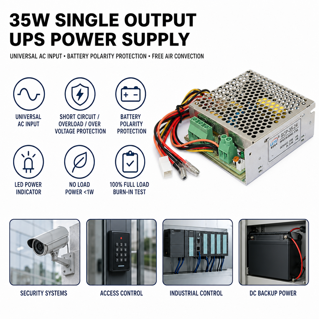
Zero power supplies ship based on theoretical simulations alone. Our dedicated aging laboratory subjects every single produced batch of EDR, MDR, LDV, and SP units to 100% full-load thermal burn-in under elevated ambient temperatures to weed out early infant mortality defects.
Backed by veteran power electronics engineers boasting 5+ years of direct SMPS topology experience, we design custom output voltages, current limit thresholds, bespoke terminal block configurations, tailored sheet metal casings, and private-label silk-screening within rapid turnaround windows.
High-performance power supply reliability is not inspected into the product at the loading dock—it is systematically built into each manufacturing step. We execute an uncompromising 8-stage quality protocol:
Direct, technically detailed answers to critical questions faced by hardware procurement managers, electrical contractors, and distribution network executives.
