Precision Step-Down & Switching Power Architectures
Explore high-yield AC-DC step down transformers, buck power topologies, and industrial DIN rail converters manufactured in an onsite-audited facility.
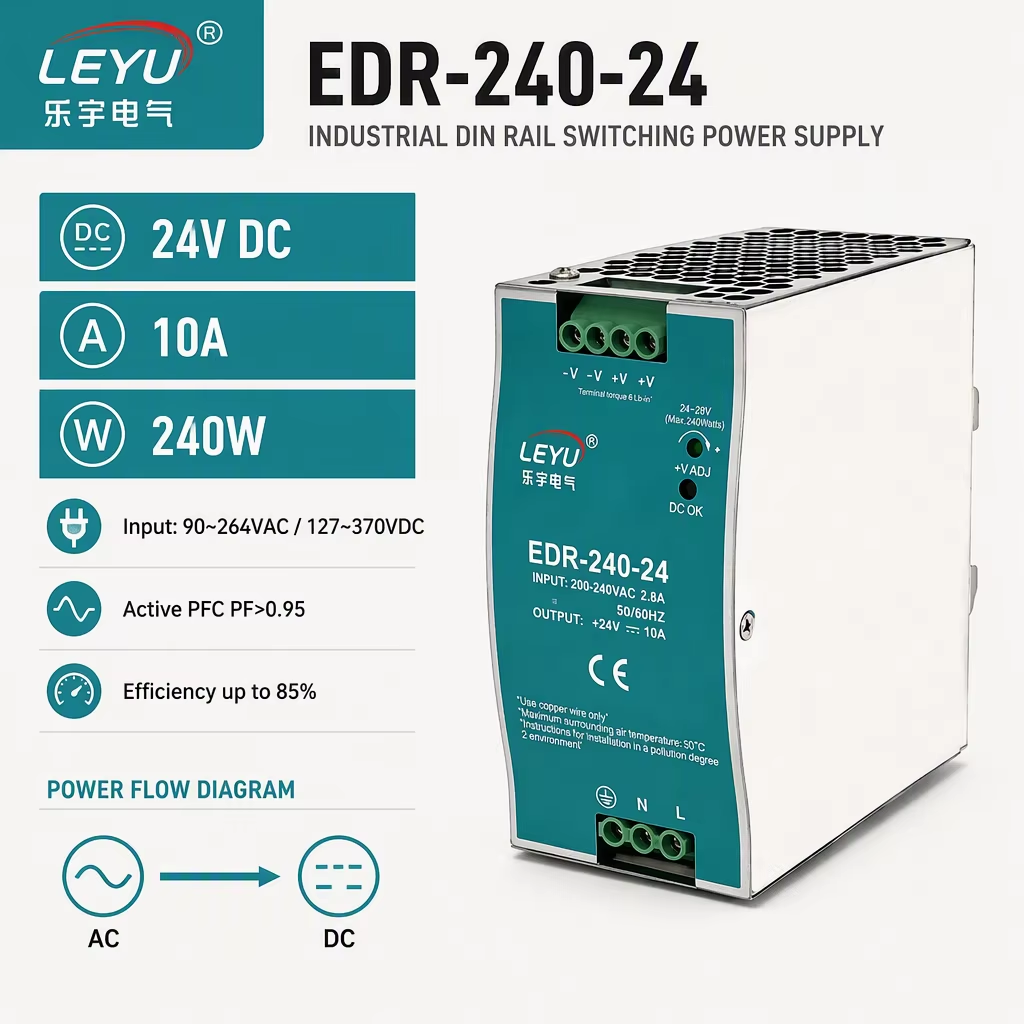
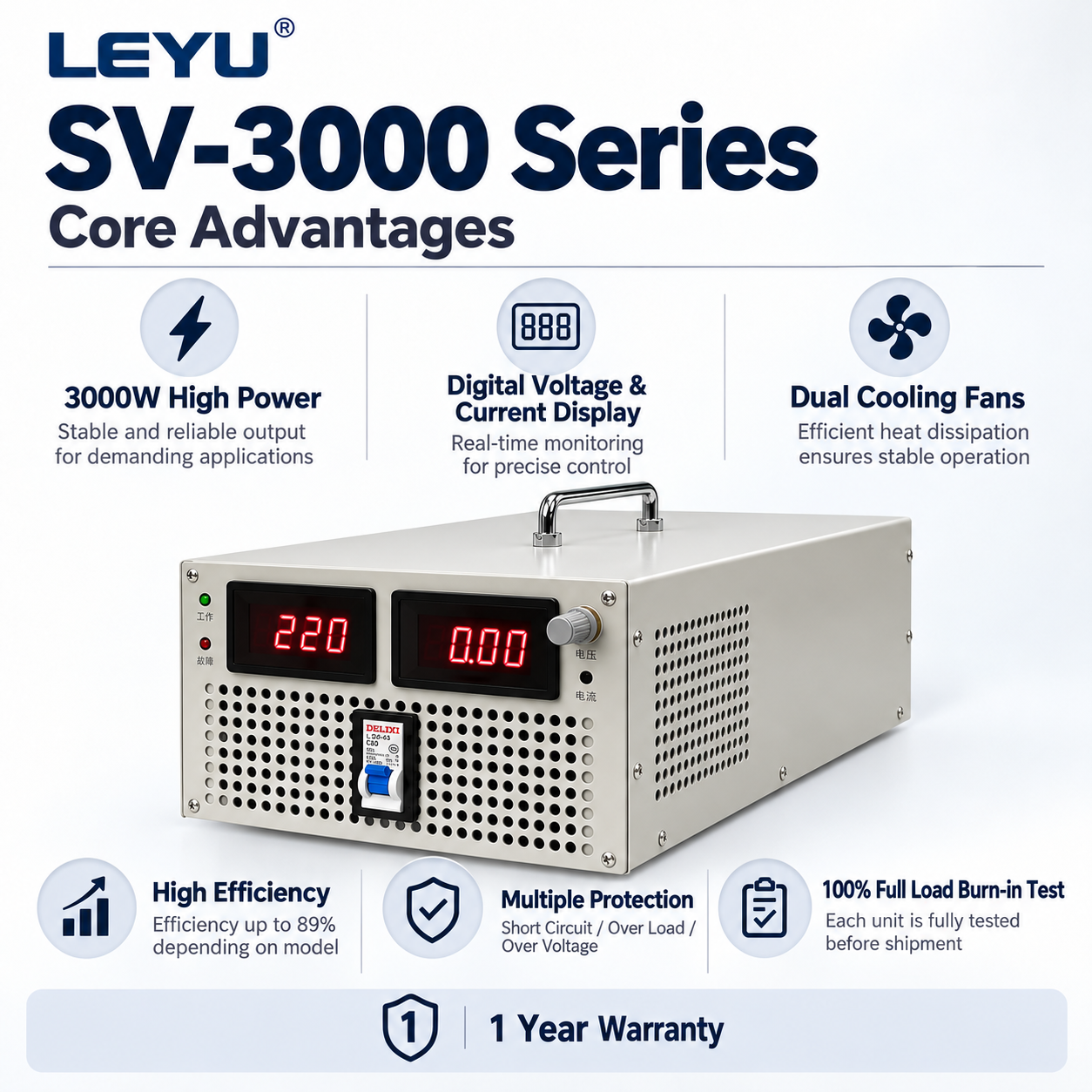
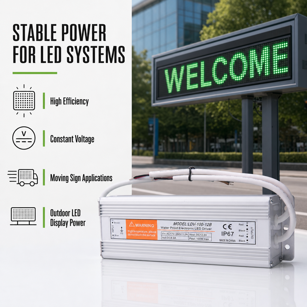
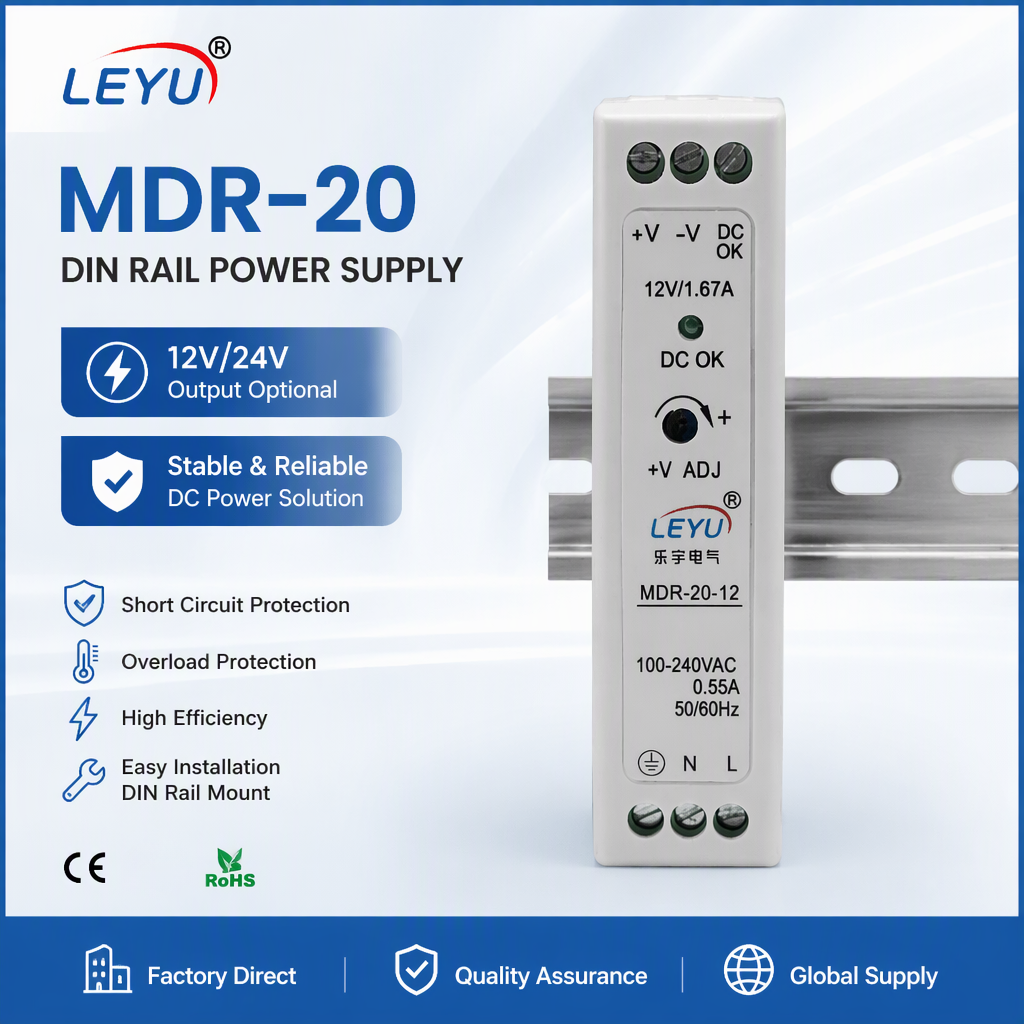
Why Yueqing Keldan Technology Excels as an OEM Partner
Direct manufacturer operations eliminate broker markups, streamline circuit redesigns, and enforce stringent quality gates from raw capacitor acceptance to burn-in tests.
In-House SMT & AOI Flow
Equipped with high-speed surface-mount placement lines and automated optical inspection systems, our Yueqing facility eliminates dry joints and misalignment before wave soldering.
TÜV Rheinland Audited
Our manufacturing capacity, legal status, and QA documentation have undergone rigorous onsite inspection by TÜV Rheinland, validating our tier-1 OEM/ODM export standards.
100% Thermal Burn-In
Every single step-down unit, industrial SMPS, and inverter undergoes complete full-load aging under elevated ambient chamber conditions to eliminate infant mortality defects.
Engineering-Led Support
Our senior engineering core holds over 5+ years of SMPS and buck topology experience, allowing rapid turnaround on custom voltage rails, form factors, and pinout adaptations.
Comprehensive Guide to Custom OEM Step-Down Converters: Topologies, Thermal Management, and Procurement Strategies
In the landscape of modern electronics—ranging from complex Industrial Internet of Things (IIoT) control cabinets and telecommunication transceivers to high-capacity battery management systems (BMS)—the requirement for clean, stable, and highly efficient DC voltage conversion is critical. A step-down converter (widely recognized across the electrical engineering sector as a buck converter) performs the vital role of taking a higher, unregulated DC or rectified AC input voltage and dropping it down to a strictly stabilized lower output voltage.
Unlike archaic linear regulators that dissipate surplus voltage entirely as waste thermal energy (operating according to Ohm's law where power dissipated equals current multiplied by the voltage drop: \(P = I \times \Delta V\)), modern switched-mode step-down topologies utilize high-frequency switching circuits (typically running from 50 kHz to well over 1 MHz), magnetic storage inductors, fast-recovery switching diodes or synchronous MOSFETs, and bulk filtering capacitors. The result is power efficiency ratings consistently spanning between 88% to 96%, minimizing thermal footprints and enabling compact system integration.
1. Essential Circuit Topologies: Buck, Synchronous Rectification, and Isolated Flyback
When engineering customized power hardware for mission-critical industrial applications, choosing the optimal converter topology dictates the bill of materials (BOM), mechanical volume, electromagnetic interference (EMI) performance, and total thermal dissipation profile.
| Converter Architecture | Typical Conversion Efficiency | Galvanic Isolation | Standard Input/Output Range | Primary Application Profile |
|---|---|---|---|---|
| Non-Synchronous Buck | 82% – 89% | Non-Isolated | In: 12V–48V DC / Out: 3.3V–24V DC | Cost-sensitive automotive ancillaries, auxiliary fan controllers, low-power relay drives. |
| Synchronous Rectification Buck | 90% – 96% | Non-Isolated | In: 12V–72V DC / Out: 1.2V–12V DC | High-current microprocessors, FPGA core rails, telecom line cards, dense edge computing. |
| Isolated Switched-Mode (Flyback/Forward) | 85% – 92% | Yes (1.5kV – 4kV AC) | In: 85V–264V AC or 48V–110V DC / Out: Multi-Rail | Industrial PLC backplanes, medical instrumentation, rail transit controls, outdoor signage. |
| Interleaved Multi-Phase Buck | 92% – 97% | Non-Isolated | In: 12V–48V DC / Out: Sub-1V to 5V (High Amp) | High-end graphic rendering hardware, heavy industrial automation controllers exceeding 60A. |
The standard non-synchronous buck converter utilizes an active switching element (usually an N-channel power MOSFET) in tandem with a freewheeling Schottky barrier diode. When the switch conducts, current ramps linearly through the inductor, energizing the magnetic core while delivering current to the load capacitor. When the primary transistor disengages, the magnetic field in the inductor collapses, forcing current forward through the diode. The major bottleneck in this layout lies within the forward voltage drop of the diode (\(V_f \approx 0.4\text{V} - 0.7\text{V}\)). At currents exceeding 10A, this equates to 4 to 7 watts of direct thermal generation at the diode alone.
For custom OEM requirements where enclosed rack space is severely restricted or cooling relies solely on natural air convection, Synchronous Rectification is mandatory. This design substitutes the freewheeling diode with a secondary low-resistance MOSFET characterized by ultra-low on-state resistance (\(R_{DS(on)}\) typically in the single-digit milliohm realm). By alternating the gate drives through dead-time logic circuits to eliminate cross-conduction shoot-through, conduction losses plunge dramatically, elevating overall conversion efficiency above 95%.
2. Thermal Dissipation and Magnetics Optimization
The operational lifespan of switched-mode power equipment is strictly governed by Arrhenius' Law: for every 10°C drop in internal capacitor and junction operating temperature, operational mean-time-between-failures (MTBF) doubles. In custom OEM step-down converter production, component layout and thermal dissipation routing are just as critical as mathematical schematic design.
Yueqing Keldan Technology achieves high thermal stability by engineering multi-layer heavy copper PCBs (2oz to 3oz outer and inner layers) paired with strategic thermal vias clustered beneath the drain tabs of primary switching MOSFETs. By conducting localized heat into the ground planes and aluminum chassis shells, our designs avoid internal thermal hotspots. Furthermore, our magnetic cores are wound using high-saturation magnetic alloys (Sendust, Kool Mµ, or high-permeability manganese-zinc ferrites) that resist saturation when subjected to sharp peak current inrushes characteristic of motorized loads and inductive solenoids.
3. Mitigating Electromagnetic Interference (EMI) and Ripple Suppression
High-speed switching transitions (\(dV/dt\) and \(dI/dt\)) create undesirable high-frequency harmonic spectrums capable of compromising sensitive communication equipment. Industrial buyers must ensure their custom OEM suppliers incorporate adequate electromagnetic compatibility (EMC) filtering into the initial printed circuit architecture:
Differential Mode vs. Common Mode Filtering: Differential noise generated along the current paths is filtered by utilizing Pi-filter arrangements (\(C\text{-}L\text{-}C\)) composed of multi-layer ceramic capacitors (MLCC) characterized by ultra-low Equivalent Series Resistance (ESR) paired with toroidal chokes. Common-mode interference transmitted across ground loops is counteracted through symmetrical bifilar-wound common-mode inductors and safety-rated Y-capacitors tied securely to chassis ground.
Future Sourcing & Procurement Trends in Power Conversion
Key market movements and component selection dynamics procurement managers must navigate through 2026 and beyond.
Wide-Bandgap Semiconductors (GaN & SiC)
Global procurement teams are shifting toward Gallium Nitride (GaN) and Silicon Carbide (SiC) switches. These components deliver dramatically faster switching times and negligible reverse-recovery losses, allowing magnetics to shrink by 40% while operating cleanly at higher ambient temperatures.
Modular DIN Rail Form Factors
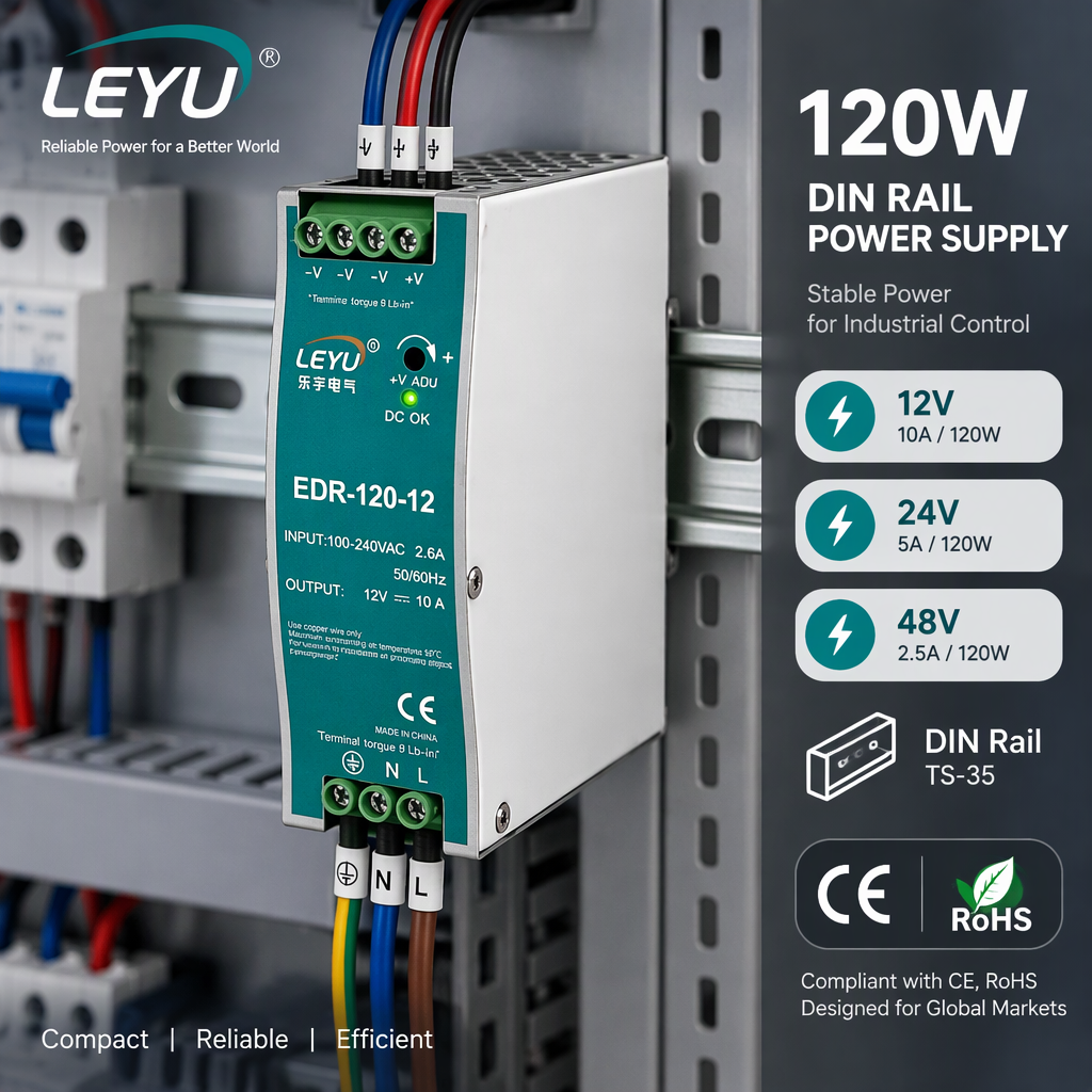
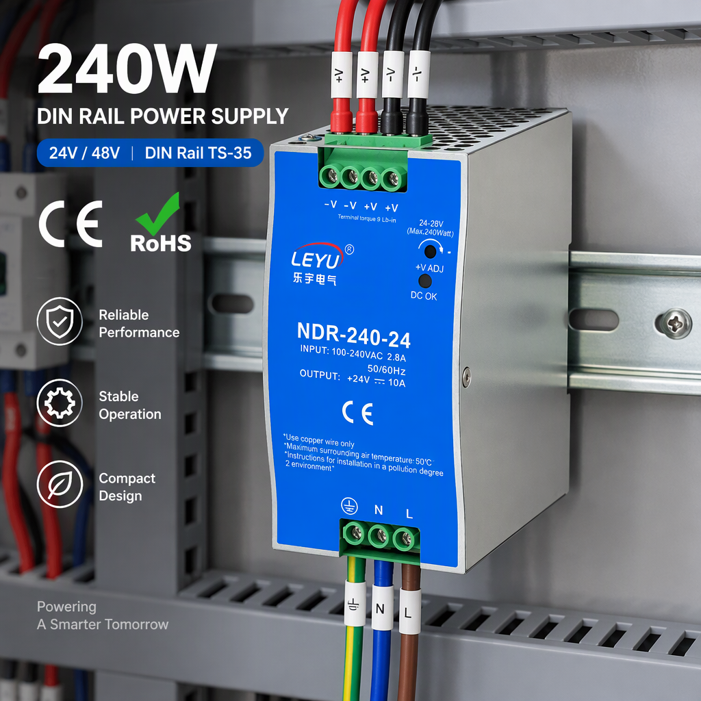
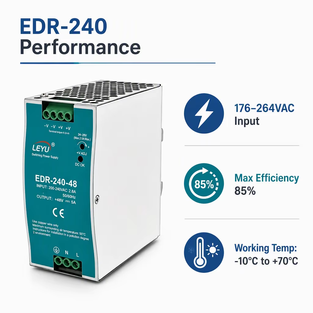
Cabinet integrators are actively transitioning away from bespoke loose-board internal converters toward toolless TS35 DIN rail snap-mount units. Modular snap-in buck modules accelerate deployment, reduce maintenance downtime, and provide standardized external wiring terminations.
Unified Safety & Harmonic Standards
Cross-regional compliance with EN 61000-3-2 (harmonic current emissions), IEC/EN 62368-1 (audio/video, information and communication technology equipment), and industrial UL 508 standards is now expected as an out-of-the-box baseline by multinational B2B purchasers.
Engineering Roadmap & Technology Advancements
How next-generation power electronics design is transforming buck regulators into intelligent, software-monitored sub-systems.
Digital Power Telemetry (PMBus)
Analog PWM control loops are yielding to programmable digital controllers. Modern step-down units incorporate I2C/PMBus communication protocols, enabling real-time voltage trimming, operating temperature logging, and predictive maintenance diagnostics directly to host PLCs.
Planar Magnetics Integration
Traditional bobbin-wound wire transformers are being superseded by multi-layer planar copper PCBs. This architecture ensures high manufacturing repeatability, exact inductance values, superior thermal conductivity, and a significantly flatter form factor.
Solid-State Electrolytic Capacitors
Liquid electrolytic capacitors represent the most common point of long-term failure due to electrolyte dry-out in elevated temperatures. The adoption of solid conductive polymer capacitors drastically lowers ESR and elevates service life well beyond 100,000 continuous hours.
Frequently Asked Questions on Sourcing Custom Step-Down Converters
Practical answers to the technical and commercial concerns most frequently raised by international engineering and sourcing directors.
Need a Custom Voltage Rail or Specialized Step-Down Form Factor?
Collaborate directly with our Yueqing power electronics engineering team. Supply your input voltage boundaries, required output load currents, target thermal parameters, and dimensional constraints for an engineering appraisal and transparent quotation.
